
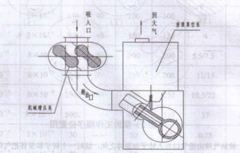
This series of Roots pump has a pair of synchronous high-speed rotors inside the pump, which achieve suction and discharge when the rotors are rotating. Since it works in the low pressure intensity range, the free path of gas molecules is larger and the resistance of gas leakage through tiny gaps is large, thus a high compression ratio can be obtained.
It can be used as a booster pump in series with the pre-stage pump, which can be used as a slide valve pump or rotary vane pump, water ring pump, oil ring pump and other vacuum pumps, but cannot directly discharge the gas into the atmosphere.
Main Features:
- Wide range of applications: such as chemical medicine, food, electrical equipment manufacturing, vacuum metallurgical industry, vacuum degassing, vacuum melting, vacuum treatment of steel, and insensitive to small amounts of dust, high ultimate vacuum. when it is used in series with the former pump, the ultimate vacuum is between 0.0004 ~ 0.0001 Torr. Check Here with detail Applications on High Vacuum.
- The ZJP series itself is equipped with a relief valve for automatic protection, which is safe and reliable.
- There are no sliding parts in the pump cavity, so no oil lubrication is required, and contamination of the system by oil vapor is avoided.
- The rotating parts are processed with high precision and finely balanced, and have good geometric symmetry, so the operation is smooth, high speed, low noise and vibration, and the operation and maintenance cost is very low compared with other pumps of the same efficiency.
- The pump drive has a reliable clearance elimination structure, so it can work under high differential pressure for a long time.
- Quick start, can reach the ultimate vacuum in a short time.
- Compact structure and small area.
Working Principle
This series of Roots pump works according to the principle of Roots Blower. As shown in the figure below: Pump working sequence position diagram.
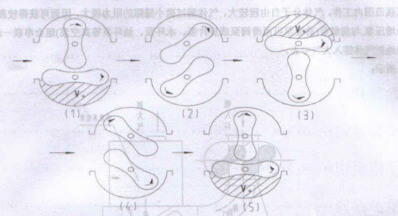
During operation, the pumped gas enters between the rotor and the pump body directly from the inlet, when a rotor and the pump body separate the gas from the inlet, and the separated gas is sent to the exhaust port during the continuous rotation of the rotor.
In Figure 1, the Vo space is in a closed state, so there is no compression or expansion. However, when the peak part of the rotor turns to the edge of the exhaust port, the position of Fig. 2, the gas diffuses from the exhaust port to the Vo area in order to make the pressure uniform in the connected volume because the pressure in the Vo part is lower than the pressure in the exhaust port.
When the rotor turns to the position of Figure 3 again, the gas at Vo is compressed to the exhaust port to discharge it, then the other side of the rotor in Figure 4 is connected to the inlet part of the gas intake, when the rotor keeps rotating to repeat the above pumping process, the pumped gas is continuously discharged.
This working process is equivalent to the increase of rotor space from a minimum value to a maximum value, and then from the maximum value to a minimum value, which is the principle of volumetric action of this series of pumps.
When this series of pump works under low inlet pressure, the rotor speed is very high, reaching 2860RPM, and the linear speed on the rotor surface is close to the thermal movement speed of molecules, then the gas molecules colliding on the rotor are carried by the rotor to the exhaust port with higher pressure, and then removed by the former vacuum pump. This is the molecular action principle of this series pump.
Under these two working principles, this series of pump has the characteristics of large pumping speed, smooth pumping curve and low energy consumption compared with other pumps under the same ultimate vacuum.
The bypass valve principle, with P series mechanical booster pump with a bypass valve on the bypass line between the outlet and the inlet, this bypass valve controls the differential pressure between the pump outlet and inlet does not exceed the rated value, such as 2666 Pa. When more than the rated value, the valve automatically opens, and the pump outlet and inlet are connected, at this time the pump works almost under the constant differential pressure load, when the differential pressure is lower than the rated value, the valve automatically closes again.
According to the characteristics of this series of pumps, you can freely choose to use different pre-stage pumps according to the different conditions of operation. Especially when the vacuum level is not high, but it is required to remove a large amount of water vapor or a small amount of dust and slightly corrosive gas, it can be used with bipolar water ring vacuum pump and piston vacuum pump.
Of course, the ultimate vacuum level achieved is lower and the power ratio is different. Our company can select various sets of this series of pumps according to the different requirements and conditions of vacuum equipment performance.
Partial List of Pump Performance Specification
| Model | Vacuum Limit | Pumping rate (L/s) | Differential pressure of overflow valve(HPa) | Matching power(Kw) | Recommended to use with front stage pump |
| ZJP-150B | 0.03HPa/0.0002Torr | 150 | 40 | 3 | 2H-15/2H-30 |
| ZJP-300B | 0.03HPa/0.0002Torr | 300 | 40 | 4 | 2H-30/2H70 |
| ZJP-600B | 0.1HPa/0.0008Torr | 600 | 27 | 7.5 | H70 |
| ZJP-1200C | 0.1HPa/0.0008Torr | 1200 | 27 | 11 | H-150 |
| ZJ-150B | 0.03HPa/0.0002Torr | 150 | 100 | 3 | 2H-15/2H-30 |
| ZJ-300B | 0.03HPa/0.0002Torr | 300 | 80 | 4 | 2H-30/2H70 |
| ZJ-600B | 0.1HPa/0.0008Torr | 600 | 50 | 7.5 | 2H-70/H-150 |
| ZJ-1800 | 0.01HPa/0.00008Torr | 1800 | 30 | 18.5 | ZJ-300/H-150 |
Installation Instruction
- Before installation, check that all parts of the pump are not damaged, and check whether the order contract is in line with the product.
- The pump must be installed in a clean environment with no or little dust and a place where it is not easy to stain the medium. The suction port of the pump should be installed with additional devices according to the use condition, such as the former pump with oil seal mechanical pump, which can be installed with dustproof device.
- The operating temperature of the pump is 5-40℃
- Pump foot installation, according to the use of the situation can be installed on a concrete foundation or steel foundation, but must be calibrated level, because the two ends of the pump clearance is very little, so the level requirements are very high, otherwise it will seriously affect the vacuum degree.
- The inlet and exhaust piping should be guaranteed to be sealed, even a small leak can affect the vacuum level.
- In principle, the length of the pipeline should be as short as possible, with fewer joints and elbows, and the diameter of the pipeline should not be smaller than the inlet diameter of the pump.
- In the middle of the pipe connecting this series pump and the previous pump, it is better to install a section of flexible hose, such as using metal bellows, etc. In order to connect and prevent damage to this series of pumps due to the vibration of the preceding pump.
- In the inlet and exhaust piping of the pump, it is better to install vacuum valve in order to maintain the vacuum in the pump chamber after stopping.
- The cooling water inlet pipeline should be equipped with a valve, which can adjust the amount of water and control the temperature of the cooling water outlet between 20-40℃ at work, noting that the water temperature should not exceed 40℃ to avoid generating dust and scale in the water jacket.
- The pump must have a pre-vacuum pump as its pre-stage pump, which cannot be used alone, but must be used in series, such as with an oil-sealed mechanical vacuum pump as the pre-stage pump. Therefore, it is also not suitable for pumping high oxygen content, explosive, corrosive to ferrous metals, chemical reaction to vacuum oil, and dusty gas, otherwise it will affect the service life of the former pump.
Operation Instruction
Pre-start preparation:
- Check that the cooling water pipes are clear and unobstructed.
- Check whether the lubrication inside the end cover A and end cover B is sufficient and the oil level height should reach the oil level line of the mirror.
- The externally extended shaft seal reservoir cup frequently viewed and filled with lubricant, and at the same time must be very clean and not allowed to have any hard particles. New pump should be changed to new oil in 30-50 hours of use, 1# vacuum pump oil. Later, the oil change cycle can be determined according to the use condition.
- If the intake gas has dust or other metal powder, etc., a dustproof or filtering device should be installed in front of the air inlet. If the inhaled gas is corrosive, neutralization measures must be taken.
- Check each part for looseness, and after a long period of time, remove the bypass relief valve to check for rust and corrosion.
- Check whether the motor steering is in the same direction as the arrow on the pump body.
Startup:
- Start the front stage pump.
- Open the air inlet valve of this pump.
- Open the cooling water valve and start this pump when the vessel pressure reaches the allowable starting pressure.
- The pump should run smoothly and the rotor should not have shock sound.
- No leakage of oil is allowed at the shaft seal of the pump.
- If the pump is operating with excessive partial temperature rise, sudden change in ammeter reading, irregular noise or other abnormal phenomena, the pump should be stopped immediately to check the cause.
Shut Down:
- Close the air inlet valve on the inlet line first.
- Stop this pump and close the exhaust valve.
- Stop the previous stage pump.
- Close the cooling water inlet valve.
- If you stop using it for a long time or in the cold zone, you must drain all the water in the cooling water jacket, otherwise the water in the jacket will freeze and cause the pump casting to freeze and crack.
Maintenance Instruction
- The pump room environment should always be kept clean and dry.
- Should often pay attention to the lubrication of each part, such as when found that the lubricant is not enough, should be timely replenishment, such as found that the lubricant is not clean, should be replaced in a timely way, and pay attention to the screw plug re-tightening to ensure sealing.
- For pump disassembly and assembly, see the structure diagram of each pump.
Disassembly:
- Loosen the screws to remove the end cover B.
- First loosen the screws, remove the pressure plate, take off the inner and outer jacket, and remove the gears. For the pumping capacity greater than 300L/S of this series, the gears should be installed and removed with the help of hydraulic pressure.
- Loosen the bolt to remove the bearing cover.
- Remove the lock nuts on the master and driven shafts.
- From the side cover B direction, remove the shaft rotor together.
- Remove side cover armor, screw sleeve.
Assembly: All disassembled gaskets should be carefully inspected carefully, and if damage is found, they should be replaced with new gaskets of the same material thickness when the pump is assembled. The disassembled parts should be cleaned with gasoline, carbon tetrachloride or ether and left to dry before assembly. 107 resin seal is used for the sealing surface between the pump body and the side cover, and the assembly order is exactly the opposite of the disassembly order, and the end clearance, the clearance between the rotor and the rotor, and the rotor and the pump body should be adjusted as specified.
